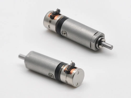
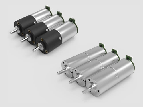
Controlling the speed of a DC motor lets you match the motor's output to the job — slowing a medical infusion pump, positioning an automotive screen, or driving a robotic joint precisely. The challenge is that a bare motor rarely runs at the speed or torque you need straight from the supply. In this guide we explain the four principal ways to control DC motor speed, how they compare on efficiency and precision, and when to use an electronic controller versus a mechanical gearbox.
On this page
- How DC motor speed is determined
- Method 1 — Electronic speed controller (PWM)
- Method 2 — Varying the supply voltage
- Method 3 — Armature voltage / resistance control
- Method 4 — Flux (field) control
- The mechanical option: gear reduction
- Comparison table & typical specifications
- FAQ
How DC motor speed is determined
The speed of a DC motor is governed by a simple relationship:
N ∝ (V − IaRa) / φ
Here N is speed, V the supply voltage, IaRa the armature voltage drop, and φ the magnetic flux. This equation tells us there are only a few things we can change to control speed: the supply voltage, the armature voltage/resistance, or the field flux — or we can hand the job to an electronic controller that modulates these automatically. These are the four methods below.
Method 1 — Add an electronic DC speed controller (PWM)
An electronic speed controller drives the motor from a fixed supply but switches the power rapidly on and off using pulse-width modulation (PWM). The percentage of time the power is "on" — the duty cycle — determines the average energy delivered, so a 50% duty cycle runs the motor at roughly half speed. Because the switching elements are either fully on or fully off, very little energy is wasted as heat, making PWM the most efficient and precise method, and the standard choice for brushless (BLDC) and modern brushed drives.
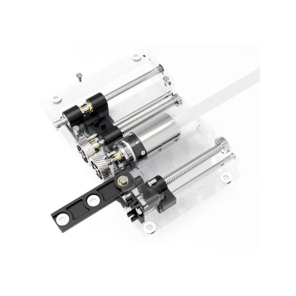
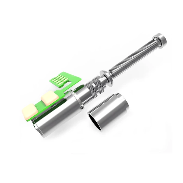
An integrated drive combines the motor, gearbox, encoder and controller in one unit. The controller reads the rotor position digitally, or through optional analog Hall sensors, and operating mode and target speed can be set through a motion manager or programming adapter. Off-the-shelf controllers are commonly rated for 6V, 12V and 24V micro motors.
[Diagram: PWM signal — fixed voltage with varying duty cycle (25% / 50% / 75%) mapped to motor speed]
Method 2 — Vary the supply voltage
Setting the load aside, a DC motor's speed is approximately proportional to the supply voltage: lower the voltage and speed falls; raise it and speed rises. This is why gear motors are offered in 6V, 12V and 24V versions. Voltage control is simple, but it has a trade-off — reducing the voltage also reduces the torque available, so it works best where the load is predictable and relatively constant.
[Diagram: speed–voltage line showing speed rising proportionally with supply voltage]
Method 3 — Armature voltage / resistance control
This method is generally used for small motors. The field winding is held at a constant supply while the armature is fed from a separate variable DC source, or a variable resistor is placed in series with the armature. Increasing the resistance lowers the voltage across the armature, and the motor slows below its normal speed. It is easy to implement, but the series resistor dissipates significant power as heat, so the method is inefficient and largely legacy — PWM is preferred in new designs.
Method 4 — Flux (field) control
In a field-wound motor, varying the current through the field winding changes the magnetic flux and therefore the speed. A variable resistor in series with the field winding adjusts this current: weakening the flux lets the motor run above its base speed, while strengthening it slows the motor down. Flux control can affect commutation and applies to field-wound machines; the flux in a permanent-magnet micro motor is fixed, so this method is not available there.
The mechanical option: gear reduction
Electronic methods control the motor itself, but in most micro drive applications speed is reduced mechanically with a gearbox (gear reducer). A set of gears lowers the output speed by the gear ratio and simultaneously multiplies torque:
Output speed = motor speed / ratio Output torque = motor torque × ratio × efficiency
For compact, low-speed, high-torque requirements, a micro gearbox is often the most convenient and cost-effective solution — and it can be paired with an electronic controller for fully adjustable, closed-loop operation.
Comparison table & typical specifications
| Method | How it controls speed | Efficiency | Best for |
|---|---|---|---|
| Electronic controller (PWM) | Switches supply at high frequency, varies duty cycle | High | Precise, dynamic control; BLDC and integrated drives |
| Supply voltage | Raises/lowers the voltage level | Medium | Simple, constant-load applications |
| Armature resistance | Series resistor drops armature voltage | Low (heat loss) | Small motors, legacy designs |
| Flux control | Varies field current / flux | Medium | Field-wound motors, speeds above base |
| Gearbox (mechanical) | Fixed gear ratio reduces speed, multiplies torque | High | Compact low-speed, high-torque micro drives |
Typical ZHAOWEI micro drive range (customizable — confirm against the datasheet):
| Parameter | Typical range |
|---|---|
| Gearbox diameter | 3.4 – 38 mm |
| Voltage | 1.5 – 24 V |
| Power | 0.01 – 40 W |
| Output speed | 5 – 2,000 rpm |
| Output torque | 1 gf·cm – 50 kgf·cm |
Conclusion
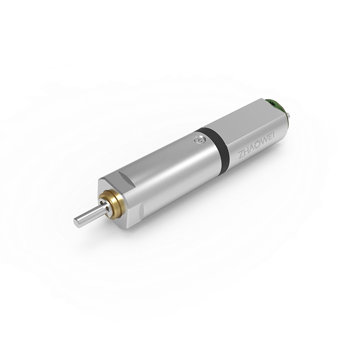
These four electronic methods cover the main ways to control DC motor speed, with PWM offering the best efficiency and precision. For compact products that need low speed and high torque, combining a micro gearbox with an integrated electronic controller is usually the most convenient and cost-effective approach. ZHAOWEI provides brushed and brushless gear motors, planetary and spur gearboxes, encoders and drive electronics as a single integrated system.
FAQ
What is the most efficient way to control DC motor speed?
PWM through an electronic speed controller, because it switches the supply rather than dissipating power as heat in a resistor.
Can a gearbox reduce motor speed?
Yes — it reduces speed by the gear ratio and multiplies torque at the same time, which is why it is so widely used in micro drives.
Does lowering voltage reduce speed?
Yes, speed is roughly proportional to supply voltage at a constant load, but available torque also decreases.
PWM vs. voltage control — what's the difference?
Voltage control changes the voltage level; PWM keeps the voltage fixed and varies the on/off duty cycle, which is far more efficient and precise.
Which voltage should I choose for a micro gear motor?
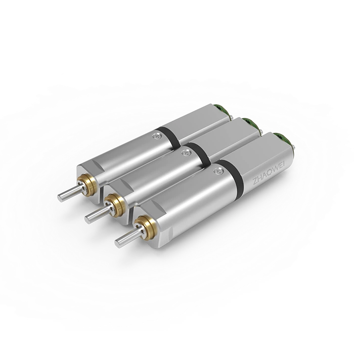
Most micro gear motors run at 6V, 12V or 24V — match it to your supply and torque needs. Custom ratings from about 1.5V to 24V are available.
Need a specific speed and torque for your product? Request a quote or download the catalog — our engineers can tailor a motor + gearbox + controller unit to your requirements.