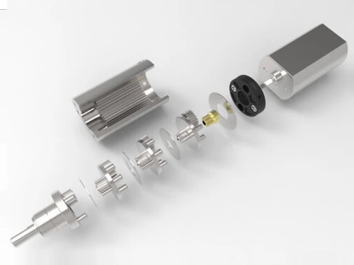
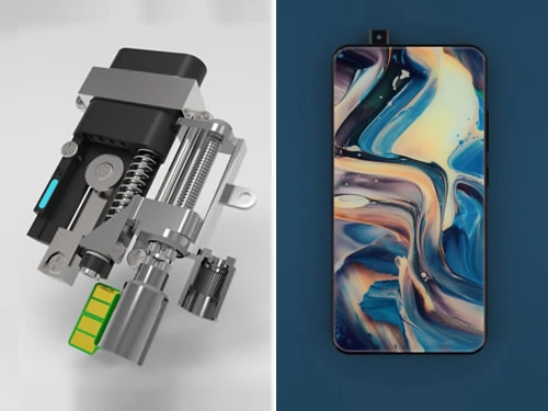
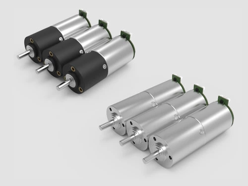
Brushless DC (BLDC) motors are widely used in robotics, industrial automation, household appliances, and compact motion-control systems. Unlike traditional brushed motors, they use electronic commutation to generate continuous rotation without mechanical brushes or a commutator.
So, how does a brushless DC motor work? A BLDC motor uses a controller to switch current through the stator windings according to the rotor's position. This creates a changing magnetic field that interacts with the permanent magnets on the rotor, producing torque and continuous rotation.
Understanding the brushless DC motor working principle helps engineers evaluate motor efficiency, speed control, torque requirements, and operating life. It also explains why BLDC motors are often combined with precision gearboxes for compact, low-speed, high-torque applications.
What Is a Brushless DC Motor?
A brushless DC motor, commonly called a BLDC motor, is an electronically commutated electric motor powered by a DC source through an electronic drive circuit. Unlike a brushed DC motor, which relies on physical brushes and a commutator, a BLDC motor uses electronic switching to control current flow.
In a typical BLDC motor, the stator contains copper windings, while the rotor carries permanent magnets. A controller energizes the stator windings in a controlled sequence to produce a changing magnetic field that drives the rotor.
Because mechanical brushes are eliminated, BLDC motors avoid brush-related friction, wear, and electrical arcing. This can support higher efficiency, reduced maintenance, and longer service life under suitable operating conditions.
For a more detailed comparison of the two motor technologies, see our guide to brushed vs brushless motors.
Main Parts of a Brushless DC Motor
The operation of a BLDC motor depends on several components working together. Although the construction varies by motor design, the main components are:
- Stator: The stationary part containing copper windings. Current flowing through the windings creates magnetic fields.
- Rotor: The rotating part containing permanent magnets that interact with the stator magnetic field to generate mechanical torque.
- Rotor Position Detection: Hall sensors, encoders, or sensorless estimation methods provide the information required for electronic commutation.
- Electronic Controller: The controller switches current between motor phases and regulates operating functions such as speed, direction, and current.
BLDC motors may use inner-rotor or outer-rotor configurations. In an inner-rotor motor, the rotor rotates inside the stator. In an outer-rotor motor, the rotor surrounds the stator. The preferred arrangement depends on packaging, thermal requirements, inertia, and application needs.
How Do Brushless DC Electric Motors Work?
The brushless DC motor working principle is based on electromagnetic interaction between the stator windings and the permanent-magnet rotor. Continuous rotation is achieved by electronically changing the stator magnetic field so that it maintains a suitable angular relationship with the rotor.
If current were continuously supplied to a fixed winding combination, the resulting stationary magnetic field would not produce sustained rotation. Instead, the controller must repeatedly change the energized phases as the rotor moves.
Step-by-Step BLDC Motor Working Principle
- DC Power Is Supplied: A DC power source supplies energy to the electronic motor controller, which contains switching devices that regulate current flow.
- Rotor Position Is Determined: Hall sensors, an encoder, or a sensorless estimation method provides information about the rotor's position.
- Stator Windings Are Energized: The controller supplies current to selected windings according to the rotor position and the selected commutation strategy.
- Magnetic Fields Generate Torque: The energized windings create a magnetic field that interacts with the permanent magnets on the rotor, producing rotational torque.
- Electronic Commutation Advances: As the rotor moves, the controller changes the phase excitation to maintain torque production.
- Continuous Rotation Is Maintained: Repeating the commutation sequence allows the rotor to rotate continuously while the controller regulates the operating conditions.
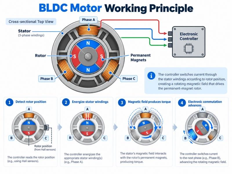
The direction of rotation can be reversed by changing the electronic commutation sequence or the commanded current relationship. Speed and torque are regulated through the controller according to the selected operating strategy.
Unlike brushed motors, BLDC motors do not require physical contact between brushes and a rotating commutator. However, they depend on suitable electronic control to maintain the correct timing and magnitude of winding currents.
How Does Electronic Commutation Work in a BLDC Motor?
Electronic commutation is the central operating feature of brushless DC motors. It replaces the mechanical current-switching function of a brushed motor with semiconductor switching devices controlled electronically.
In a typical three-phase BLDC motor, the stator windings are arranged into three electrical phases, commonly identified as A, B, and C. The controller determines which phases should conduct current according to the rotor's electrical position.
Six-Step Commutation in a Three-Phase BLDC Motor
One common control method is six-step commutation, also known as trapezoidal commutation. During each electrical cycle, the controller advances through six switching states.
In a typical two-phase conduction arrangement, one phase is connected to the positive supply, another to the negative supply, and the remaining phase is left floating.
| Commutation Step | Positive Phase | Negative Phase | Floating Phase |
|---|---|---|---|
| 1 | A | B | C |
| 2 | A | C | B |
| 3 | B | C | A |
| 4 | B | A | C |
| 5 | C | A | B |
| 6 | C | B | A |
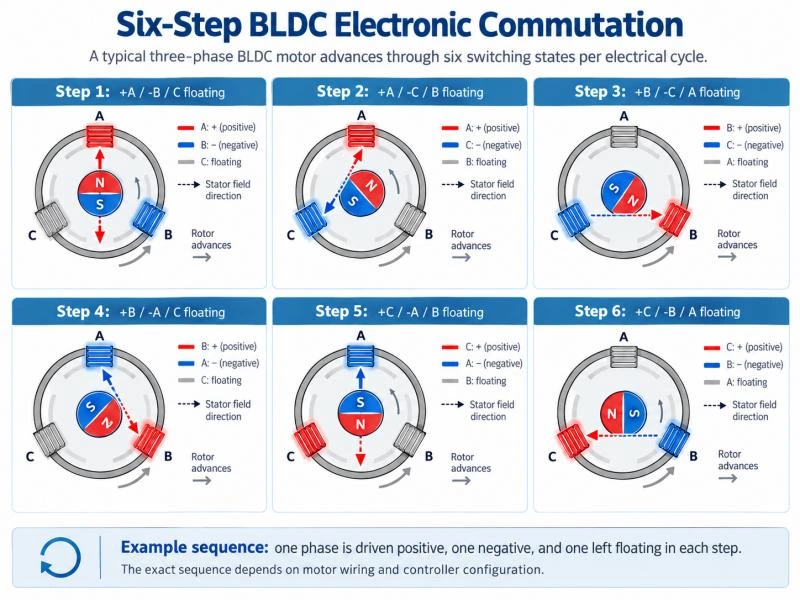
This table shows one illustrative six-step switching sequence. The actual phase sequence, switching polarity, and rotation direction depend on the motor connections and controller configuration.
Each switching state typically covers 60 electrical degrees. After six states, the controller completes one electrical cycle. The number of electrical cycles required for one mechanical revolution depends on the motor's number of pole pairs.
As the controller advances through the states, the stator magnetic field changes position, allowing the rotor to continue turning. Other BLDC control strategies, including sinusoidal commutation and field-oriented control, use different current waveforms to achieve smoother torque production.
How Does a Brushless DC Motor Controller Work?
A brushless DC motor controller, sometimes called an electronic speed controller (ESC), manages the current supplied to the motor phases.
The controller typically includes a power switching stage, gate-driving circuits, and control electronics. Its functions may include:
- Determining or estimating rotor position.
- Controlling the timing of electronic commutation.
- Regulating winding voltage and current.
- Adjusting motor speed and rotation direction.
- Providing current limiting and other protection functions.
- Processing feedback for closed-loop operation when supported.
The controller must be compatible with the motor's electrical characteristics, including rated voltage, current requirements, phase configuration, and position-feedback method.
Incorrect controller matching or unsuitable commutation settings can reduce efficiency, increase vibration, cause unstable operation, or create excessive heating.
Hall Sensor vs Sensorless BLDC Motor Control
For electronic commutation to occur at the correct time, the controller needs information about rotor position. Different detection methods are available depending on the operating requirements.
| Control Method | How It Works | Typical Considerations |
|---|---|---|
| Hall Sensors | Detect changes in the rotor's magnetic field. | Useful for startup and low-speed commutation. |
| Encoder Feedback | Provides shaft-position information to the controller. | Suitable for applications requiring finer position or speed feedback. |
| Sensorless Control | Estimates rotor position from back-EMF or other electrical measurements. | Reduces external sensors but may require more complex startup control. |
Back electromotive force, or back-EMF, is the voltage generated as the permanent-magnet rotor moves relative to the stator windings.
In conventional back-EMF-based sensorless control, the signal becomes weaker at very low speeds and is unavailable at standstill. As a result, startup often requires a dedicated control strategy before reliable position estimation is established.
Hall-sensor-based control can simplify commutation during startup and low-speed operation. However, the best feedback method depends on the required speed range, installation space, control accuracy, and system cost.
How Are BLDC Motor Speed and Torque Controlled?
Brushless DC motors can support flexible speed and torque regulation because their winding currents are controlled electronically. Motor performance depends on the interaction between the controller, available supply voltage, winding characteristics, and mechanical load.
PWM Speed Control
Pulse-width modulation (PWM) is commonly used in BLDC motor drives. The controller rapidly switches semiconductor devices and adjusts the proportion of each switching period during which voltage is applied.
By changing the PWM duty cycle, the controller influences the effective voltage and current supplied to the motor windings.
For example, under a simplified switching arrangement, increasing the PWM duty cycle generally increases the available average winding voltage. However, the resulting motor speed also depends on load, back-EMF, current limits, and the selected control strategy.
Closed-loop speed control may use feedback to adjust PWM commands automatically when mechanical load changes.
Relationship Between Motor Current and Torque
In a permanent-magnet BLDC motor, electromagnetic torque is closely related to the current component that produces torque.
Under suitable operating conditions, the approximate relationship can be expressed as:
Motor Torque = Torque Constant × Torque-Producing Current
This simplified relationship helps explain why controllers regulate motor current when torque control is required.
However, the exact relationship depends on motor construction, current definitions, commutation method, and operating conditions. Increasing current also increases winding losses and temperature, so continuous torque is limited by the motor's thermal capabilities.
Peak torque may be available for short periods, but it should not be confused with continuously rated torque.
Motor Speed, Load, and Thermal Performance
As a BLDC motor rotates, it generates back-EMF that increases with rotational speed. The available supply voltage must overcome this back-EMF and the voltage drops associated with winding resistance and inductance.
When the mechanical load increases, the motor generally requires additional torque-producing current to maintain the commanded speed.
If current, voltage, or thermal limits are reached, the controller may no longer be able to maintain the target operating point.
For engineering selection, the motor's torque-speed curve, rated current, efficiency data, duty cycle, and allowable temperature should be considered together.
Advantages and Limitations of Brushless DC Motors
Replacing mechanical commutation with electronic control provides several practical benefits, particularly in applications requiring compact construction and long operating life. However, the electronic drive also introduces design requirements that must be considered.
Advantages of Brushless DC Electric Motors
- High Efficiency: Eliminating brush contact losses can improve electrical-to-mechanical efficiency. Actual performance depends on motor design, load, speed, and controller efficiency.
- Longer Service Life: The absence of brushes removes a major wear mechanism, although bearings and other components still determine overall reliability.
- Reduced Maintenance: Brush replacement and commutator maintenance are unnecessary, making BLDC motors attractive for equipment with long operating periods.
- Flexible Motion Control: Electronic drives can regulate speed, torque, acceleration, and direction with appropriate feedback and control strategies.
- Compact Power Density: Suitable BLDC designs can deliver useful power and torque within relatively small motor dimensions.
- Reduced Brush-Related Noise: Brushless construction eliminates electrical arcing and mechanical noise caused by brush-to-commutator contact.
Limitations of BLDC Motors
- Electronic Controller Required: BLDC motors require suitable drive electronics to perform commutation.
- Higher System Complexity: Rotor-position information, switching logic, current regulation, and controller compatibility must be considered.
- Initial Cost: Electronic control components can increase total system cost compared with basic brushed motor arrangements.
- Electrical Interference: Electronic switching can generate electromagnetic interference if the drive and wiring are not properly designed.
- Thermal Constraints: Winding losses, controller losses, and cooling conditions limit continuous output performance.
Motor selection should therefore consider the complete drive system rather than evaluating motor efficiency or purchase price alone.
BLDC Motor Applications and Gearbox Integration
Brushless DC motors are widely used in equipment requiring efficient, controllable rotation. Their electronic commutation and compact construction make them suitable for a variety of consumer and industrial motion systems.
What Are Brushless DC Motors Used For?
Typical applications include:
- Robotics: Driving robotic mechanisms and compact motion assemblies requiring controlled movement.
- Industrial Automation: Supporting pumps, conveyors, feeders, and automated mechanical systems.
- Household Appliances: Providing controllable rotation in vacuum cleaners, fans, and other powered devices.
- Medical Equipment: Supporting compact mechanisms where controllability and reduced maintenance are important.
- Fitness and Massage Equipment: Driving mechanical assemblies requiring controlled speed and suitable output torque.
- Smart Devices: Operating miniature mechanisms where compact dimensions and energy efficiency are important.
The motor configuration should be selected according to operating voltage, rated speed, required torque, duty cycle, available space, and control requirements.
Why Pair a Brushless DC Motor with a Gearbox?
Brushless DC motors can operate at relatively high rotational speeds, while many mechanical applications require lower output speed and higher torque.
A reduction gearbox changes the speed and torque characteristics of the motor assembly. The approximate relationships are:
Gearbox Output Speed = Motor Speed / Reduction Ratio
Gearbox Output Torque = Motor Torque × Reduction Ratio × Gearbox Efficiency
For example, consider a BLDC motor operating at 6,000 rpm connected to a gearbox with a 100:1 reduction ratio. The theoretical gearbox output speed would be approximately 60 rpm.
If the motor delivers 0.02 Nm at that operating point and the gearbox efficiency is assumed to be 80%, the estimated output torque would be 1.6 Nm.
This example illustrates the calculation method rather than a specific product specification. Actual performance must be checked against the motor's operating curve and the gearbox's rated torque, efficiency, and thermal limits.
When selecting a geared BLDC motor, engineers should also consider backlash, transmission noise, output shaft loads, installation dimensions, and expected operating life.
ZHAOWEI Brushless DC Gear Motor Solutions
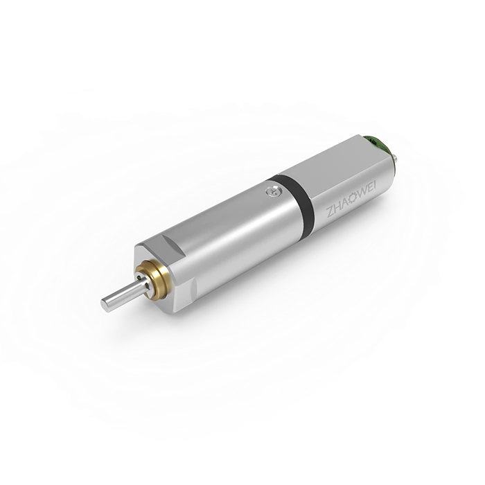
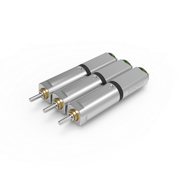
ZHAOWEI develops compact brushless DC gear motors combining BLDC motor technology with precision reduction gearboxes for applications requiring controlled low-speed output and higher torque.
Available brushless gear motor configurations include different diameters, operating voltages, reduction ratios, and output characteristics to accommodate various mechanical requirements.
For example, ZHAOWEI offers 12 mm, 16 mm, 20 mm, and other brushless gear motor configurations for compact motion systems. The appropriate assembly depends on the application's required torque, speed, duty cycle, controller, and available installation space.
Integrating the motor, controller, and gearbox as a complete drive system helps engineers evaluate the actual output characteristics rather than relying only on the motor's standalone specifications.
Frequently Asked Questions About BLDC Motors
Can a Brushless DC Motor Run Without a Controller?
A typical BLDC motor requires electronic commutation to produce sustained controlled rotation. Simply connecting fixed DC power directly to the motor phases does not provide the continuously changing excitation needed for normal operation. An appropriate controller or integrated electronic drive is therefore required.
How Does a BLDC Motor Know When to Switch Phases?
The controller determines commutation timing using rotor-position information from Hall sensors, encoders, or sensorless estimation methods. It then changes the energized phases according to the selected commutation strategy.
What Is the Difference Between Hall Sensor and Sensorless BLDC Control?
Hall-sensor control uses magnetic sensors to obtain rotor-position information, including during startup and low-speed operation. Sensorless control estimates rotor position using electrical measurements such as back-EMF. The preferred method depends on speed range, cost, space, and control requirements.
Can a BLDC Motor Be Used with a Reduction Gearbox?
Yes. A BLDC motor can be combined with a planetary, spur, or other suitable reduction gearbox to provide lower output speed and increased available output torque. The gearbox must be selected according to efficiency, allowable load, reduction ratio, backlash, and mechanical requirements.
Conclusion
Brushless DC electric motors work through electronic commutation. A controller determines the rotor position and switches current through the stator windings in sequence, creating a changing magnetic field that interacts with the permanent-magnet rotor to produce continuous rotation.
The relationship between electronic commutation, rotor-position detection, and winding current control determines how the motor responds to speed and load requirements. Understanding these operating principles helps engineers select appropriate BLDC motors and compatible controllers.
For applications requiring lower output speed and higher torque, BLDC motors can be combined with precision reduction gearboxes. ZHAOWEI provides compact drive solutions with configurable motor and gearbox combinations for different mechanical requirements.
Explore our brushless gear motor range or discuss your custom drive requirements with ZHAOWEI to identify a suitable motor, controller, and gearbox configuration.