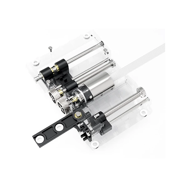
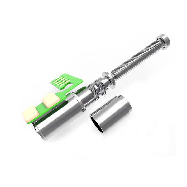
Stepper motors are brushless, synchronous electric motors that move in discrete angular steps. A stepper motor, also known as a step motor or stepping motor, converts a sequence of electrical control signals into controlled mechanical rotation. Unlike a conventional DC motor that rotates continuously when powered, a stepper motor moves between defined positions as its windings are energized in sequence.
Stepper motors contain multiple coils arranged in groups called phases. By controlling the electrical current supplied to each phase, the motor driver creates a changing magnetic field that causes the rotor to move one step at a time. The number of commanded steps determines the intended angular displacement, while the stepping frequency controls the intended rotational speed.
This operating principle makes stepper motors useful for robotics, automation, positioning mechanisms, and compact motion systems. They can provide repeatable positioning without continuous feedback when properly matched to the load. Understanding how a stepper motor works also helps engineers determine when a gearbox is needed to achieve the required output speed and torque.
How Does a Stepper Motor Work?
The working principle of a stepper motor is based on electromagnetic interaction between the stationary stator and the rotating rotor. As the driver energizes the stator windings in a controlled sequence, the resulting magnetic field causes the rotor to move through a series of stable angular positions.
Basic Working Principle
Like other electric motors, a stepper motor consists of a stationary part called the stator and a rotating part called the rotor. The stator contains magnetic poles and copper windings, while the rotor may be a permanent magnet, a toothed soft-iron core, or a combination of both.
When electrical current flows through a stator winding, the winding produces a magnetic field. The rotor responds to the resulting magnetic forces and moves toward a stable alignment position. By changing which windings are energized, the driver shifts the magnetic field and causes the rotor to move to the next position.
The basic movement process can be explained in four stages:
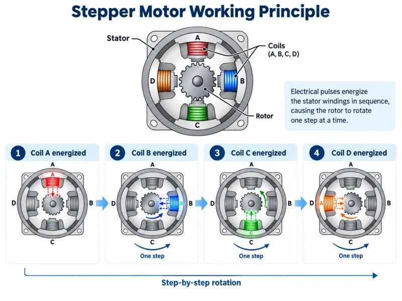
- Stator Energization: The driver supplies current to one or more stator windings, creating electromagnetic poles.
- Rotor Alignment: The rotor moves toward a position determined by the energized magnetic field.
- Phase Switching: The driver changes the winding excitation sequence, shifting the magnetic field to the next position.
- Step-by-Step Rotation: The rotor follows the changing field, producing incremental rotation. Repeating the sequence allows the motor to rotate continuously.
Reversing the excitation sequence reverses the direction of rotation. Increasing the commanded stepping frequency increases the intended speed, provided the motor can produce sufficient torque to follow the commands.
Unlike a brushed DC motor, a stepper motor does not rely on mechanical brushes and a commutator to switch current between its windings. Instead, the external driver controls winding excitation electronically.
Further Information About How a Stepper Motor Works
Stepper motors are generally classified into three types: permanent magnet (PM), variable reluctance (VR), and hybrid (HB) stepper motors. Although their rotor constructions differ, all three use controlled stator excitation to create incremental movement.
For a permanent magnet stepper motor, the rotor contains a magnet with north and south poles. When current flows through the stator windings, the resulting magnetic field interacts with the rotor magnet and causes it to rotate toward an aligned position.
As the magnetic field generated by the stator changes direction, the rotor moves to follow the next stable position. The angular movement produced by each full-step command depends on the motor's design rather than a universal fixed angle.
For example, a motor with a 1.8° full-step angle requires 200 full steps to complete one revolution. Other stepper motors may use different step angles depending on their internal construction.
By controlling the number of steps, the stepping frequency, and the winding excitation sequence, the driver determines the commanded angular displacement, speed, and direction of rotation. However, accurate open-loop movement requires sufficient motor torque to prevent missed steps.
Understanding Step Angle and Steps per Revolution
The step angle describes the angular distance a stepper motor moves during one full step. It determines the motor's basic movement resolution and is an important parameter for positioning applications.
The relationship between step angle and the number of full steps per revolution is:
Full Steps per Revolution = 360° / Step Angle
| Full-Step Angle | Full Steps per Revolution | Typical Characteristic |
|---|---|---|
| 7.5° | 48 | Relatively coarse step resolution |
| 3.6° | 100 | Moderate step resolution |
| 1.8° | 200 | Common in hybrid stepper motors |
| 0.9° | 400 | Finer full-step resolution |
For example, if a 1.8° stepper motor receives 50 full-step commands, the intended angular displacement is:
50 × 1.8° = 90°
In an open-loop system, this calculation assumes the rotor successfully follows every commanded step. Excessive load, rapid acceleration, or resonance can cause the actual position to differ from the commanded position.
Types of Stepper Motors
The three main stepper motor types use different rotor constructions to produce electromagnetic movement. Understanding their basic characteristics helps engineers select an appropriate motor for the intended application.
Permanent Magnet Stepper Motors
A permanent magnet stepper motor uses a magnetized rotor surrounded by stator windings. The rotor responds to changes in the stator magnetic field and moves between stable angular positions.
These motors are often used in compact positioning mechanisms, electronic instruments, and applications requiring relatively simple motion control.
Variable Reluctance Stepper Motors
A variable reluctance stepper motor uses a toothed soft-iron rotor without permanent magnets. The rotor moves toward the position of minimum magnetic reluctance as the stator windings are energized in sequence.
This construction allows incremental motion based on the alignment of rotor teeth and stator poles. Unlike permanent magnet designs, variable reluctance motors do not provide permanent-magnet detent torque when unpowered.
Hybrid Stepper Motors
A hybrid stepper motor combines permanent magnet and variable reluctance operating principles. Its rotor typically includes a permanent magnet and two toothed rotor sections arranged with an angular offset.
The interaction between the rotor teeth and stator magnetic poles allows relatively fine step angles and useful torque characteristics. Hybrid designs are commonly used in CNC equipment, 3D printers, robotics, and industrial positioning systems.
How Are Stepper Motors Controlled?
A stepper motor requires a driver to regulate current through its windings and advance the magnetic field in the correct sequence. Different drive modes determine how the motor moves between its magnetic positions.
Full-Step, Half-Step, and Microstepping
Several excitation methods are used to control stepper motors. They differ in the number of intermediate commanded positions, the current supplied to the windings, and the resulting motion characteristics.
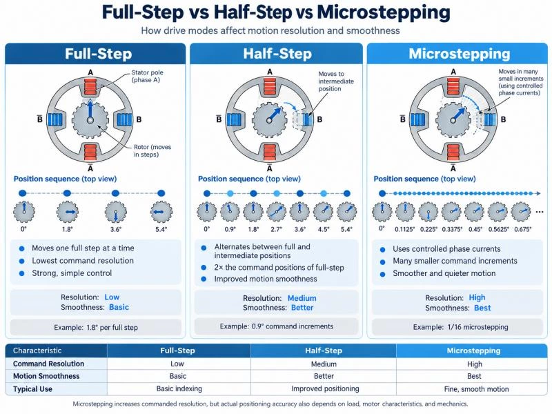
| Driving Mode | Working Principle | Main Characteristic |
|---|---|---|
| Wave Drive | Typically energizes one phase at a time | Simple excitation, with torque depending on motor design and current |
| Full-Step | Advances between full-step equilibrium positions | Uses the motor's nominal full-step resolution |
| Half-Step | Creates intermediate positions through an alternating excitation sequence | Provides twice the nominal command resolution |
| Microstepping | Regulates phase currents to establish intermediate magnetic field positions | Smaller command increments and generally smoother motion |
For example, a 1.8° stepper motor requires 200 full steps per revolution. When using half-step control, it has 400 nominal command positions per revolution.
With 1/16 microstepping, the same motor receives 3,200 microstep commands per revolution, corresponding to a nominal command increment of 0.1125°.
However, microstepping increases commanded resolution rather than guaranteeing equivalent absolute positioning accuracy. Actual movement depends on load torque, current regulation, friction, and motor characteristics.
Open-Loop and Closed-Loop Stepper Motor Control
Stepper motors are frequently used in open-loop control systems. The controller sends stepping commands and estimates the rotor position by counting the commanded movements from a known reference position.
Open-loop operation eliminates the need for continuous position feedback, simplifying the system. However, if the motor cannot generate sufficient torque at the required speed, it may lose synchronization with the commanded steps.
Closed-loop stepper motor systems use feedback devices, such as encoders, to monitor actual rotor movement. This allows the control system to detect position deviations and respond according to the driver's capabilities.
The appropriate control method depends on the application's accuracy requirements, load changes, speed, and tolerance for missed steps.
Stepper Motor Torque, Speed, and Positioning Accuracy
Understanding how a stepper motor moves is only one part of motor selection. Its actual performance also depends on available torque, operating speed, acceleration, and the mechanical load.
Holding Torque and Running Torque
Holding torque is the maximum static torque a powered stepper motor can resist at a specified position under defined conditions. It is useful for evaluating whether the motor can maintain a stationary load.
Running torque describes the torque available while the motor is rotating. A stepper motor's available torque generally decreases as speed increases because winding inductance limits how quickly current can rise during each excitation interval.
For this reason, holding torque should not be used as the only criterion for selecting a stepper motor. Engineers should review the motor's torque-speed curve together with the driver voltage, current settings, and intended operating conditions.
Why Do Stepper Motors Lose Steps?
A stepper motor can lose steps when the required load torque exceeds the torque available at the commanded speed. Excessive acceleration may also prevent the rotor from following the changing magnetic field.
Common causes include:
- Load torque exceeding available motor torque.
- Acceleration or deceleration that is too rapid.
- Operation near problematic resonance frequencies.
- Incorrect driver current settings or inadequate supply voltage.
- Mechanical friction, binding, or unexpected load changes.
Missed steps can cause positioning errors in open-loop systems because the controller may continue counting commands without detecting that the rotor has fallen behind.
Suitable motor sizing, acceleration profiles, drive settings, and feedback control can help reduce this risk.
Step Resolution vs Positioning Accuracy
Step resolution and positioning accuracy are related but different characteristics.
Step resolution describes the smallest nominal movement increment that the drive system can command. Positioning accuracy describes how closely the actual mechanical position matches the target position.
Even when microstepping provides very small command increments, errors can arise from motor construction, load torque, friction, mechanical compliance, and missed steps.
In a geared stepper motor system, gearbox backlash and transmission errors must also be considered. A smaller theoretical output step does not automatically guarantee a corresponding improvement in absolute positioning accuracy.
Where Are Stepper Motors Used?
Stepper motors are widely used in applications that require incremental movement, repeatable positioning, or controlled low-speed operation.
- 3D Printers: Controlling print-head movement, build-platform positioning, and filament feeding.
- CNC Machines: Driving machine axes and positioning mechanisms where the motor's torque and speed capabilities meet the required operating conditions.
- Robotics: Providing controlled movement in small robotic joints, positioning devices, and automated mechanisms.
- Medical Equipment: Supporting controlled motion in pumps, adjustment mechanisms, and positioning assemblies.
- Camera and Optical Devices: Driving compact focusing, adjustment, and positioning mechanisms.
- Industrial Automation: Operating feeders, indexing mechanisms, compact actuators, and other repeatable motion systems.
For applications requiring higher torque at reduced speed, a stepper motor can be combined with a precision reduction gearbox.
When to Equip the Stepper Motor with Gears?
To achieve high-performance operation in compact motion systems, engineers should determine whether a stepper motor can directly meet the required output torque and speed or whether an additional planetary or spur gearbox is necessary.
A reduction gearbox can increase available output torque while reducing rotational speed. It can also change the load inertia reflected to the motor, helping the drive system handle certain mechanical loads more effectively.
However, the gearbox introduces mechanical losses and transmission errors. Its reduction ratio, efficiency, backlash, load capacity, and service life must therefore be considered during motor selection.
Role of the Gears in Stepper Motors
The primary function of a reduction gearbox is to reduce output speed and increase available torque. This is useful in applications requiring high mechanical force and controlled low-speed movement.
For example, if a stepper motor rotates at 600 rpm and is connected to a 10:1 gearbox, the theoretical gearbox output speed is approximately 60 rpm.
The approximate output torque can be calculated using:
Output Torque = Motor Torque × Gear Ratio × Gearbox Efficiency
For a motor producing 0.05 Nm of torque, a 10:1 gearbox with an assumed efficiency of 80% would provide a theoretical output torque of approximately 0.4 Nm.
This is an illustrative calculation rather than a product specification. Actual performance depends on operating conditions, gearbox efficiency, and the allowable torque rating of the gearhead.
A reduction gearbox also changes the mechanical load inertia reflected to the motor. For an idealized rigid transmission, reflected load inertia decreases approximately with the square of the reduction ratio. This can help improve the motor's ability to accelerate certain loads, although the gearbox's own inertia and mechanical losses must also be considered.
Why Low Backlash Matters for Stepper Gear Motors
As stepper motors are often selected for positioning applications, gearbox accuracy becomes particularly important.
Backlash is the clearance between mating gear teeth that can produce lost motion when the direction of rotation changes. Excessive backlash can reduce output positioning repeatability, even when the stepper motor itself receives accurate control commands.
For this reason, precision stepper gear motor systems often require carefully selected gearheads with suitable backlash characteristics, torque capacity, efficiency, and service life.
Gear reduction can improve theoretical output movement resolution, but the practical positioning performance depends on the entire mechanical assembly.
Choosing a Geared Stepper Motor for Your Application
When selecting a stepper motor with a gearbox, the motor and transmission should be evaluated as a complete drive system.
Important selection parameters include:
- Output Torque: Continuous and peak torque required by the load.
- Output Speed: Required rotational speed after gear reduction.
- Gear Ratio: Appropriate reduction ratio for the motor's operating range.
- Backlash: Acceptable lost motion during direction reversal.
- Load Inertia: Effects of the mechanical load on acceleration and stability.
- Installation Space: Motor diameter, gearbox length, shaft configuration, and mounting requirements.
- Operating Conditions: Temperature, duty cycle, noise, and expected service life.
ZHAOWEI develops precision gearheads for stepper motor applications, with configurations designed to support compact dimensions, suitable torque transmission, low noise, and different reduction ratios.
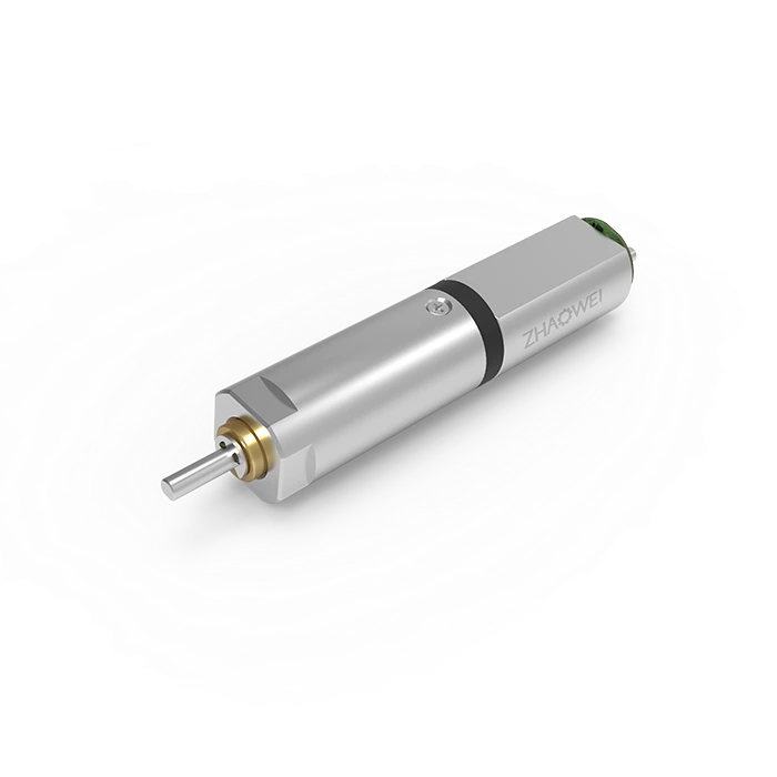
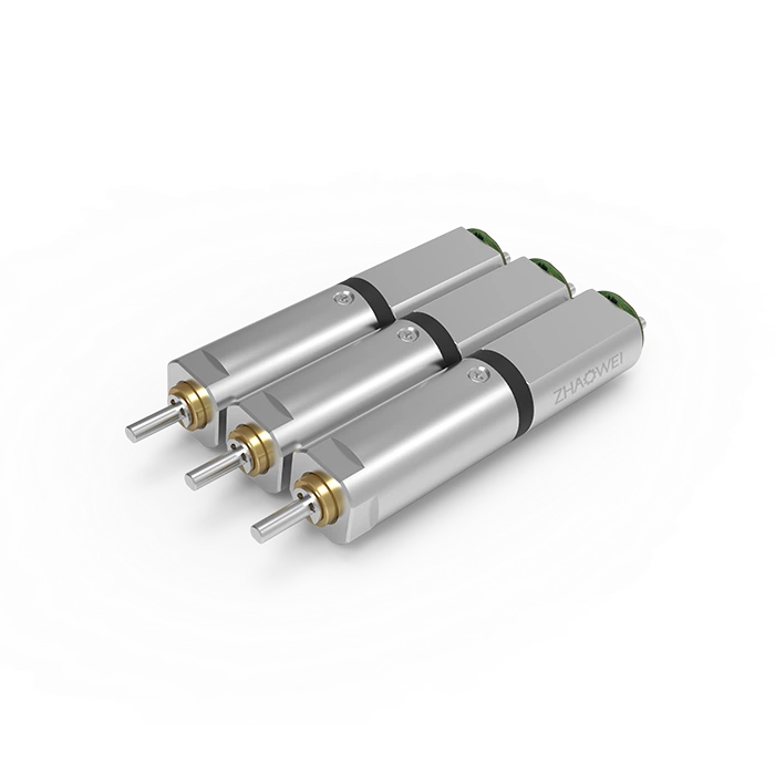
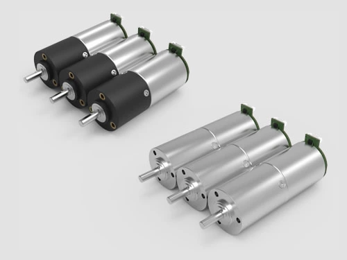
Its micro stepper gear motors combine stepper motors with planetary or spur gearboxes for low-speed, high-torque positioning applications.
For example, the 8 mm Stepper Gear Motor is a compact option available with different reduction configurations. The final motor and gearbox combination should be selected according to the application's load, speed, and dimensional requirements.
Frequently Asked Questions About Stepper Motors
How Many Steps Does a Stepper Motor Take per Revolution?
The number of full steps per revolution depends on the motor's step angle. For example, a 1.8° motor requires 200 full steps per revolution, while a 0.9° motor requires 400. Half-stepping and microstepping increase the number of commanded increments.
Can a Stepper Motor Work Without an Encoder?
Yes. Stepper motors can operate in open-loop systems without continuous position feedback. The controller determines the intended position by counting steps from a known reference. However, missed steps can cause positioning errors, so closed-loop feedback may be beneficial in demanding applications.
Why Does Stepper Motor Torque Decrease at Higher Speeds?
Stepper motor torque generally decreases as rotational speed increases because winding inductance limits the rate at which current can rise. At higher stepping frequencies, the winding current may not reach the level needed to maintain low-speed torque. Driver design, supply voltage, and motor characteristics influence the torque-speed curve.
Does a Gearbox Improve Stepper Motor Accuracy?
A reduction gearbox decreases the angular movement of its output shaft for each motor step, increasing theoretical output resolution. However, actual positioning accuracy depends on backlash, transmission error, load conditions, and motor performance. A properly selected low-backlash gearbox can support more repeatable positioning.
Stepper Motor Solutions from ZHAOWEI
Stepper motors provide controlled incremental movement for precision positioning, automation, and compact mechanical systems. Their performance depends on the motor construction, driver, operating conditions, and mechanical load.
For applications requiring low output speed and higher torque, integrating a suitable precision gearbox can help the motor meet specific motion requirements.
ZHAOWEI develops compact stepper gear motor solutions with configurable reduction ratios, output torque characteristics, dimensions, and mechanical interfaces. Its precision transmission capabilities support applications where compact installation and reliable motion are important.
Explore ZHAOWEI's stepper gear motor solutions or discuss your custom drive requirements to identify a suitable motor and gearbox configuration for your project.